Increasing the capacity of a gantry crane—from 10 tons to 20 tons, 50 tons, 100 tons, or even heavier—requires far more than upgrading the hoist or using stronger wire ropes. Capacity enhancement is an engineering and structural transformation that impacts every part of the crane’s mechanical, structural, and electrical design. Whether upgrading an existing crane or designing a new high-capacity gantry crane from scratch, engineers must evaluate how additional loads influence stresses, stability, fatigue life, safety factors, and long-term performance.
This article examines the key structural design considerations involved in increasing gantry crane capacity, with a focus on steel structure optimization, load path engineering, stability control, wheel and rail interfaces, and modern safety technologies. Understanding these factors helps ensure that cranes can safely lift heavier loads while maintaining reliability, operational efficiency, and compliance with global industrial standards.
1. Understanding the Relationship Between Load and Structural Response
The structural behavior of an overhead gantry crane for sale is directly tied to the loads it carries. When capacity increases, several forces rise proportionally or exponentially:
-
Vertical loads (self-weight + lifted load)
-
Dynamic loads (impact factor, hoist acceleration/deceleration)
-
Horizontal loads (braking forces, trolley traveling forces, wind loads)
-
Torsional loads (asymmetric lifting, skewing forces)
-
Fatigue loads over repeated duty cycles
Increasing capacity does not simply mean choosing thicker steel; it requires a complete structural analysis to ensure the entire load path—from hoist to girder to legs to wheels—can withstand higher forces. This is the foundation of all further design decisions.
2. Optimizing the Main Girder for Higher Load Capacity
The main girder is the primary load-bearing component of a gantry crane. Increasing capacity demands modifications across several aspects:
2.1 Girder Type Selection
-
Single girder: suitable up to around 20–32 tons
-
Double girder: preferred for 20–500 tons
-
Box-type girder: ideal for heavy-duty and long-span applications
-
Truss girder: used for large spans but not preferred for heavy loads
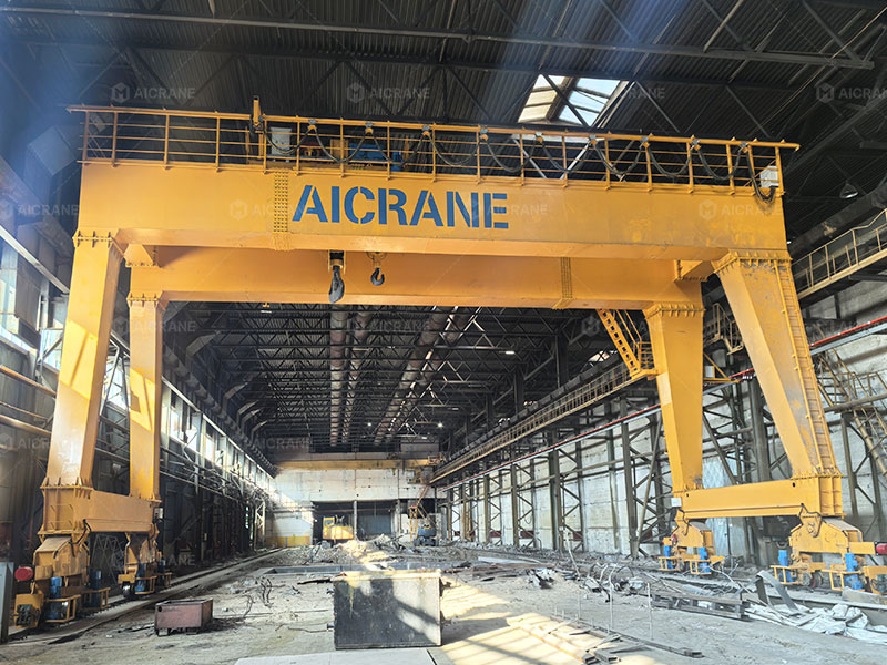
When capacity increases, engineers often transition from single girder to double girder gantry crane or from truss design to welded box design to achieve higher rigidity and bending resistance.
2.2 Section Modulus and Bending Strength
A higher lifting capacity requires increasing the section modulus, which may involve:
-
Increasing girder height
-
Strengthening flanges
-
Reinforcing web plates
-
Adding internal stiffeners to reduce shear deformation
Finite Element Analysis (FEA) is typically performed to simulate stress distribution under maximum load.
2.3 Fatigue Resistance
Heavy-duty cranes (A5–A7 work duty) operate under high load cycles. Structural members must therefore be designed for:
-
Reduced weld stress concentration
-
High fatigue-resistant weld profiles
-
Durable steel materials with superior toughness
Fatigue is especially critical for heavy duty gantry cranes used in precast plants, steel mills, ports, and container yards.
3. Strengthening the Gantry Legs and Support Frames
As the main girder carries more weight, the gantry legs must also be reinforced to maintain structural stability.
3.1 Increased Cross-Section and Stronger Bracing
Higher loads demand:
-
Thicker leg plates
-
Larger box-legged structures
-
Diagonal bracing for torsional stiffness
-
Improved connection plates and high-strength bolts
3.2 Load Transfer to the Ground
The crane legs transfer all loads to the wheels and ultimately the foundation. Therefore, engineers must analyze:
-
Stress concentrations at joints
-
Buckling risk under vertical compression
-
Torsional forces from uneven loading
Without proper leg engineering, even the strongest girder cannot reach full capacity.
4. Wheel, Rail, and Ground Interface Reinforcement
4.1 Wheel Load Analysis
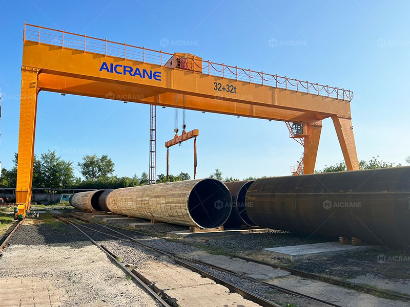
Wheel loads increase proportionally with crane capacity. For example:
-
A 20-ton gantry crane may have wheel loads around 50–60 kN
-
A 100-ton crane can exceed 200–300 kN per wheel
Therefore:
-
Wheel diameter, width, and material hardness must increase
-
Wheel bearings must handle higher radial and axial forces
4.2 Rail and Beam Strengthening
For rail-mounted gantry (RMG) cranes:
-
Rails may need increased size (e.g., from QU70 to QU120)
-
Rail pads and clips must withstand higher horizontal forces
-
Girder end trucks require stronger welded connections
4.3 Ground and Foundation Requirements
Heavier cranes require:
-
Improved concrete foundations
-
Soil compaction analysis
-
Ground reinforcement (especially for RTG cranes)
Ignoring ground conditions can cause crane skewing, derailment, or structural damage.
5. Trolley and Hoist System Upgrades
Increasing capacity means upgrading all components of the lifting mechanism:
5.1 High-Capacity Hoist
Heavier loads require:
-
Larger drums
-
Higher-strength wire ropes
-
Multi-reeving systems
-
Larger motors with improved thermal performance
5.2 Trolley Frame Reinforcement
Since the trolley carries the hoist, it must resist:
-
Bending stresses
-
Wheel loads
-
Torsional vibration
Heavy-duty trolleys typically use box-structure frames instead of angle-steel designs.
5.3 Improved Braking and Drive Systems
Stronger cranes need:
-
Service brakes, emergency brakes, and anti-fall devices
-
Heavy-duty motors and geared drives
-
Variable Frequency Drives (VFDs) to control sway and shock loads
6. Stability and Anti-Sway Engineering
With higher loads, the risk of sway, overturning, and skewing increases. Structural upgrades must therefore include:
6.1 Wind Load Resistance
Cranes operating outdoors, especially at ports or construction sites, must withstand:
-
Higher wind pressures
-
Stronger gust responses
-
Storm conditions
Design improvements include:
-
Enlarged end-tie beams
-
Additional bracing
-
Wind-proof rail clamps
-
Storm locking devices
6.2 Sway Control
Structural stiffness plays a major role, but modern systems such as:
-
VFD-controlled motors
-
Sway reduction algorithms
-
Active damping systems
help ensure safe and precise load movement.
7. Safety Factor and Compliance Requirements
High-capacity gantry cranes must meet global standards including:
-
FEM (Europe)
-
ISO
-
CMAA (America)
-
GB/T (China)
When capacity increases:
-
Safety factors must be recalculated
-
Allowable deflection limits become stricter (e.g., L/800)
-
Redundancy is added in critical points such as hoist brakes and limit switches
Safety is not just a matter of compliance but essential for preventing structural failure.
8. Considerations When Upgrading an Existing Gantry Crane
Retrofitting an existing crane to increase capacity is more complex than building a new one. Engineers must assess:
-
Original design limits
-
Steel material properties
-
Fatigue history
-
Hidden cracks or weld failures
-
Foundation suitability
-
Age and performance of electrical systems
Often, capacity upgrades require extensive reinforcement or full replacement of critical parts. In many cases, building a new crane is more cost-effective.
Conclusion
Increasing the capacity of a gantry crane requires a comprehensive structural redesign that strengthens the girder, legs, trolley, drive systems, wheels, and foundation. Engineers must evaluate the entire load path and incorporate advanced analysis methods, high-strength materials, fatigue-resistant welding, and modern safety technologies. By addressing these key structural design considerations, industrial users can confidently operate higher-capacity gantry cranes with improved reliability, safety, and operational efficiency.